
Compact HF antennas for Amateur Radio
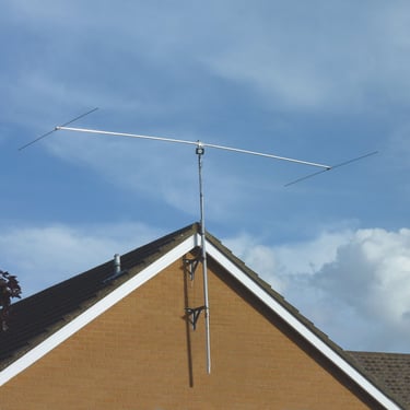
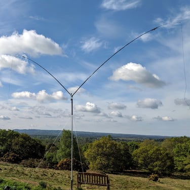
Gallery


Shop at ML&S
Reviews
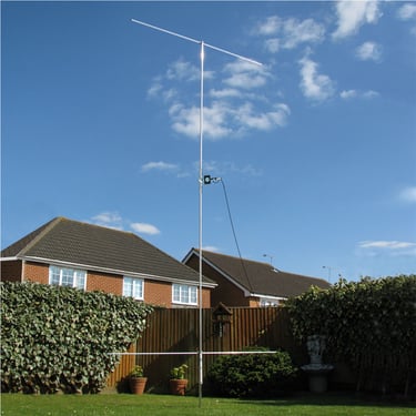
"Hi Tony, just letting you know I’m enjoying the Dual Beam Pro and it is great in comparison to the cobweb.
Well the bands are not great but I managed to do some good qso in digital and ssb. Great work keep doing it."
Marco - 2E0BJL - Epsom, UK
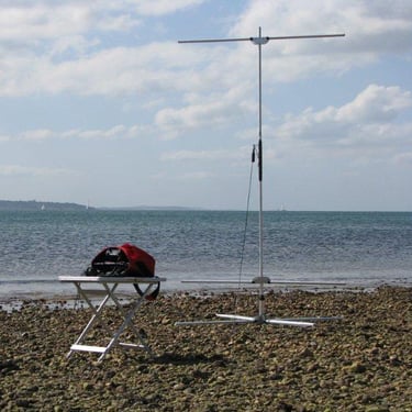
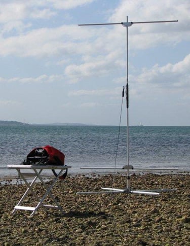
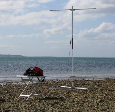
"What did strike me during the tests was how easy the Traveller is to erect and, as it is freestanding, how effective it is without needing high supports or ground radials. This really can be put up in a small back garden or park, or on the beach, for an afternoon's HF DXing without too much trouble."
Radcom magazine
Support
proantennas@gmail.com
+44-7470 337050
© 2025. All rights reserved.